Standard 1-D collimation geometry (USAXS)
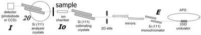
The X-ray beam travels from right to left, from the Advanced Photon Source source toward the detector. It first passes through a side reflecting mirror (not shown in drawing), double-bounce Si(111) monochromator and beam-defining slits.
The USAXS instrument begins downstream of these optics. The beam then passes through a horizontally reflecting Si(220) channel-cut crystal (four reflections), an ion chamber used as an intensity monitor, guard slits, and finally the sample.
After the sample, scattered radiation is analyzed by a second horizontally rotating Si(220) channel-cut crystal (also four reflections) and measured with a photodiode detector. During scans, both the analyzer crystal and photodiode translate horizontally as the analyzer rotates, maintaining the required alignment in the large-angle instrument geometry. Combined with the high flux at the sample (approximately 10¹² photons/s), this configuration extends the measurable q-range into values typical of conventional SAXS, around 0.3 Å⁻¹.
The photodiode detector is linear over at least nine decades of intensity, enabling measurements across a very wide dynamic range. It can also be replaced by a CCD camera for imaging or radiography. This mode is commonly used for sample alignment and locating regions of interest with a precision of approximately 10 µm.
USAXS-SAXS-WAXS
In addition to the above described USAXS instrument our current instrument has additionally 500mm long pinhole SAXS and 300mm long WAXS (XRD, powder diffraction) devices. Below is updated schematics showing, that only device can be in position at time, therefore data re collected sequentially.

2-D collimation (side-bounce) geometry - currently not available
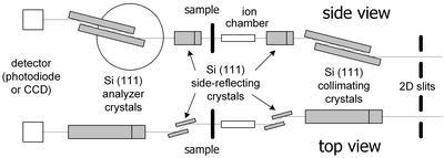
In this setup two side reflection stages (Si 220 channel-cuts) are added – one before the ion chamber and one after the sample. These channel-cuts define the beam in the horizontal direction, effectively removing the slit smearing. This comes at a cost of some loss of intensity and Q range, therefore this configuration is appropriate only in selected cases – especially for anisotropic samples where small Q range and high Q resolution are needed – basically with for anisotropic samples with large scatterers…